____________________ > Atlanta
> System components
> Old Style
> Hydrolic Components
> Low presure Components
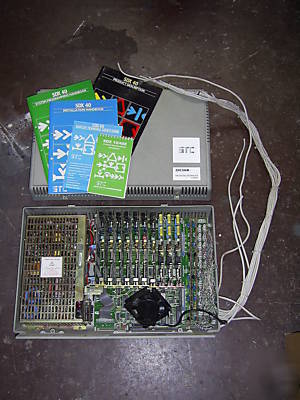
> Stc SDX40E/180 telephone system
Stc SDX40E/180 telephone system
SDX40E telephone system made by STC Telecommunications Ltd.
APPROVAL No. NS/3841/3/E/600032 was NS/2334/3/E/600032
Renamed as the SDX 40 in 1985 it is a pre-programmed key telephone system utilising microprocessor control techniques. The basic system comprises of one Control Unit and supports up to 20 devices. A device can consist of an exchange line, a private circuit or a terminal which may be one of a range of key station instruments or 2 wire approved apparatus.
The SDX40 (shown right and easily identifiable by the blue ribbon cable connecting the two units) was superseded by the SDX40E, which was technically superior. This had a two 2 meg backplane which was extended by means of two black cables to the extension units.
Up to two Extension Control Units (ECU) can be used to increase the system size to 60 devices. Both Control Units incorporate 240v AC power supply units and all power requirements are provided from the 240v AC mains.
The SDX 20 has the same functionality as the SDX 40E system but does not have the ability to support ECU's, and so is limited to a capacity of 20 devices.
Visual indications of call state, call identity, system time and mode of operation are provided by alpha-numeric and symbol displays on the FT-2, FT-3 and FT-4 terminals. These also provide special connection facilities selected by push button keys. The basic FT-1 terminal is not equipped with feature keys or displays. It functions as a push button telephone with limited access to features and facilities of the SDX.
The FT-5 and DSS/BLF unit provide visual indication of the status of devices, and allow them to be directly selected. The FT-5 provides selection for up to 14 devices from a key terminal. The DSS/BLF is used in association with a key terminal. The DSS/BLF main unit provides selection for up to 28 devices and a DSS/BLF extension unit for a further 30 devices.
A power-fail feature enables one or more standard telephones to be connected to the system, in the event of a power failure these are connected directly to the exchange lines allowing incoming or outgoing calls to be made.
Interconnection between the SDX and the PSTN, Speechband Private Circuits or host CRA is via BT 239A connectors on the MDF/TJF connector block located inside the SDX Control Unit and Extension Control Unit. Alternatively, a separate Test Jack Frame may be used comprising a suitable connection box with BT 237A connection strips, connected within 15 metres of the SDX system.
The apparatus is approved for use in the Simple Call Routing Mode (SCRM).
Each cabinet can only have a maximum of 5 analogue trunk cards installed and they should be install in the first 5 equipment slots.
SDX 40 Socket Wiring for featurephones
Twisted pair cable must be used and telephone extension leads must not be used.
SDX 40 Socket Wiring for 2 wire telephones
A & B of the exchange line are connected to MDF 1 & 4.
2cct Subscriber Line Card (SLC - Terminal)
1cct or 2cct SLT Card (two wire POT or TAMS)
2cct LD/MF switchable trunk card
DSS Card, supports one key phone port and one DSS port
The SDX systems get very hot - position them carefully -
preferably on an open wall or a very well ventilated room.
It was working when the system was decommissioned.