____________________ > Ava
> System components
> New Style
> Hydrolic Parts
> T870A bga irda welder infrared heating rework station
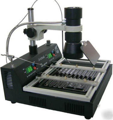
T870A bga irda welder infrared heating rework station
T870A BGA IRDA Welder Infrared Heating Rework Station
4 Don't need weld tools.This machine can weld all the component of 35-50cm.
6 Infrared heating don't have sirocco flow. Don't impact perimeter small component.Can suitable for all of the component,especially Micro BGA component.
1.Inspect the machine and then open it
(1) Check if the connection wire of the lamp body, the Temp-sensor and power cable is ok.
(2) Turn on the power switch. Allow the T-870A Power-On-Self-Test (POST) to complete. After this, Temperature set-points will display last value used.
(3) The front panel has two switches, controls the preheating dish and the infra-red lamp body separately;
2. PC Board Component Removal and Replacement
Put the PCB board on the PCB board holder , rotate the holder fasten nut , fasten it. Move the PCB board holder to choose the right position.
(2)the Process of unsoldering and repairing
Adjust the position of the PCB board, make the chip at the centre of the lamp light. Adjust the height of the lamp body, keep the lamp 20-30mm from the chip.
Put the temp-sensor at the edge of the chip, lay a bed of solder flux around the chip and on the temp-sensor, it will make the measured temperature more accurately, at the same time the solder flux will make the soldering chip more perfect, and keep the bonding pad away from conglutinating and having tin wool.
According to the producing technological requirement or the size of PCB board, adjust the pre-heat dish temperature(adjustable 60-200 ).
When there is waterproof solid sealing compound on the chip, please open the pre-heat dish to pulverize the solid sealing compound first, then clean it up. You may adopt other method as sol/hydrosol. When you adopt the method we supplied, you had better choose the temperature between 100 and 140 according to the producing technological requirement or the size of PCB board, control the pre-heat time 3-5 minutes(the temperature will be steady) or longer.
Otherwise if the chip is without waterproof solid sealing compound or the PCB board is small, then it won t transmutation, we needn t open the pre-heat dish
According to the producing technological requirement or the size of chip, choose the suitable temperature of the IR-lamp.
Usually, when the chip size is less than 20*20mm, we adjust the IR-lamp temperature 220-240 , and if the chip is without waterproof solid sealing compound or the PCB board is small, then it won t transmutation, we needn t open the pre-heat dish. Otherwise, we should adjust the pre-heat temperature to 100-120 .
When the chip is lager than 30*30mm,we should adjust the pre-heat temperature to 120-140 first, wait 3-5minutes and the temperature will be steady. Then adjust the IR-lamp temperature to 240-260 , we will complete the unsoldering and repairing process conveniently. Attention: At the time, the light is strong, the temperature rises quickly, we should pay our attention on controlling, avoid the Temp-sensor displacement, reflect on the temperature measuring. We should also pay our attention on time controlling, avoid burning out the chip.
When achieving the set-up lamp temperature, Once the solder liquefied and melted, use tweezers to remove the chip.
3.the Process of Soldering a chip
It is generally the same as the (2)Process of unsoldering and repairing , but you should do as follows:
Clean the target pad with the brush
Then put the solder ball and a flat of solder flux and the chip on the target pad
Turn on the switch of the pre-heat dish, and set-up the temperature
Turn on the switch of the IR-Lamp, Regulate the temperature (the temperature must be warm enough to liquefied the solder), focus the Infrared light on the chip to be solder
Wait to allow the Infrared lamp to heat the solder flux to work as the solder balls on the target chip pad reaches liquid temperature. Use tweezers or a vacuum device to place the chip target position. Once the solder liquefies, the chip will be sold automatically.
After cooling the chip, pick up the PCB board, check if it is ok. If not, re-operate.
About the components without plumbum, you should add 20-30 .
4. the Process of soldering kinds of Plug (as: GAP platoon expansion slot plug of the computer motherboard)
Usually we cover the hardware and the PCB board (which won t be maintained) with the aluminium-foil paper, Then put the PCB board on the holder, fasten it. Turn on the Pre-heater dish and adjust the temperature at 160-180 , Put the Temp-sensor at the side of the part which is being unsoldering, and it will up to the temperature in 3-5minutes. Then you can unsoldering the parts.
In special circumstances, you can open the IR-Lamp to heating the part, and it will be unsoldering quickly.
About the PCB board with components on its both side, please set-up the pre-heat temperature lower, and then use the IR-Lamp to heat.
Turn off the switch of the pre-heat dish and the IR-lamp.
Once the machine is cooling enough, cut off the power cable.
When you maintain some large chip of the PCB board such as the mother board of the computer, you must pre-heat and dry the whole board first, then you can avoid the transmuting of the PCB board and soldering joint and rake angle of the chip.
All the plastic plug-in board must be covered with aluminium-foil paper, to avoid transmutation or destroying.
The PCB board which had been maintained, after cooling, clean it, and do the test when it is dry. If it is not ok, re-soldering it.
Around working, when the PCB board is not on the holder, please do not long time open the IR-lamp, do not shoot the light on the strong glisten objects. Otherwise it will reduce its using time.
About the chips which is encapsulation simply, please pre-stick aluminium-foil paper on the centre of the chip, to avoid burning out the slice of silicon.
The measurement of the aluminium-foil paper had better a little larger than the slice of silicon, but not too large. Otherwise, it will do effect on the soldering.
1.At all times Insure the light body cooling fan is unobstructed and clean.
2.Use a little machine oil. Lubricate the focus holder and cell guide to inhibit rusting, keep them ease to operate.
3. Clean the Lamp body especially the lens and the pre-heat dish with the absolute alcohol, clean out the condensate of the welding flux. Keep the IR-thermal radiation without blocking.
The T-870A System creates temperatures in excess of high degrees via Infrared Light. Wear appropriate eye protection or any device within the T-870A when using it. After use, Do not cut the power immediately, confirm the light body is cool-to-touch, cut the power, then place the system in airiness & safety storage.
Do NOT use this system or any associated device in an environment conducive to fire or electrical overload.
Disconnect the AC Power Plug when not in use.
When using, it is of high temperature, Do NOT allow children or the un-trained to touch the T-870A.
Cut off the power if it isn t be used.
Statement If there is any difference between user operating manual and actual product, according to the actual product !
details detailsdetails detailsdetails detailsdetails details
details detailsdetails detailsdetails detailsdetails detailsdetails detailsdetails detailsdetails detailsdetails detailsdetails detailsdetails detailsdetails detailsdetails detailsdetails detailsdetails detailsdetails detailsdetails detailsdetails detailsdetails detailsdetails detailsdetails details