____________________ > Abingdon
> System components
> Old Style
> Tools
> Toroid core for power transformator
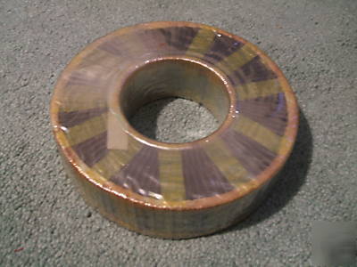
Toroid core for power transformator
Dimensions are OD 5.3/8 inches, ID 2.3/8 inches and height 1.3/8 inches weight 6 lb.
The formulas for the imperial (inch) system are still being used in the United States by many transformer manufacturers. Most steel EI laminations used in the US are measured in inches. The flux is still measured in gauss or Teslas, but the core area is measured in square inches. 28.638 is the conversion factor from 6.45 x 4.44 (see note 1). The formulas for sine wave operation are below. For square wave operation, see Note (3):
N={\frac {E 10^8} {{28.638 f B a}}} \!
T={\frac {10^8} {{28.638 f a B}}} \!
B={\frac {E 10^8} {{28.638 f N a}}} \!
a={\frac {E 10^8} {{28.638 f B N}}} \!
To determine the power (P) capability of the core, the core stack in inches (D), and the window-area (Wa) product, the formulas are:
P={\frac {fBWa} {{17.26S}}} \!
Wa={\frac {17.26SP} {{fB}}} \!
D={\frac {17.26PS} {{WCfB}}} \!
* P is the power in volt amperes or watts,
* S is the current density in circular mils per ampere (Generally 750 to 1500 cir mils),
* W is the window area in square inches,
* C is the core width in square inches,
* D is the depth of the stack in inches and,
* Wa is the product of the window area in square inches multiplied by the core area in square inches. This is especially useful for determining C-cores but can also be used with EI types.
A shorter formula for the core area (a) and the turns per volt (T) can be derived from the long voltage formula by multiplying, rearranging, and dividing out. This is used if one wants to design a transformer using a sine wave, at a fixed flux density, and frequency. Below is the short formulas for core areas in square inches having a flux density of 12 kilogauss at 60 Hz (see note 2):
a={0.1725 {\sqrt{P}}} \!
T={\frac {4.85} {{a}}} \!
And for 12 kilogauss at 50 Hz:
a={0.206 {\sqrt{P}}} \!
T={\frac {5.82} {{a}}} \!
* Note 1: The factor of 4.44 is derived from the first part of the voltage formula. It is from 4 multiplied by the form factor (F) which is 1.11, thus 4 multiplied by 1.11 = 4.44. The number 1.11 is derived from dividing the rms value of a sine wave by the its average value, where F = rms / average = 1.11.
* Note 2: A value of 12 kilogauss per square inch (77,400 lines per sq. in.) is used for the short formulas above as it will work with most steel types used (M-2 to M-27), including unknown steel from scrap transformer laminations in TV sets, radios, and power supplies. The very lowest classes of steel (M-50) would probably not work as it should be run at or around 10 kilogauss or under.
* Note 3: All formulas shown are for sine wave operation only. Square wave operation does not use the form factor (F) of 1.11. For using square waves, substitute 4 for 4.44, and 25.8 for 28.638.
* Note 4: None of the above equations show the stacking factor (Sf). Each core or lamination will have its own stacking factor. It is selected by the size of the core or lamination, and the material it is made from. At design time, this is simply added to the string to be multiplied. Example; E = 4.44 f N a B Sf